| C.M.S.
Module 1067 contains two independent envelope generators
designed for use in the CMS Euro-Rack Modular system.
The ARP Module 1033 is
a functional circuit package designed for use in the
ARP Series 2000 Electronic Music Synthesizers. This
module contains two identical delayed-gate exponential
envelope generators.
The 1033 Dual Delayed Gate
Envelope Generator is usually used with voltage-controlled
filters, amplifiers, and other modules requiring triggered
control signals. For instance, when used with ARP Module
1006 Filt-Amp, the 1033 Envelope Generator can be used
to control the amplitude envelope or timbre variations
of signals passing the Filt-Amp with respect to time.
The delayed-gate feature permits the user to delay the
beginning of an envelope so that complex amplitude and
timbre characteristics may be synthesized.
An exponential envelope
generated by the ARP 1033 Module may be defined by four
adjustable parameters: Attack Time, Initial Decay Time,
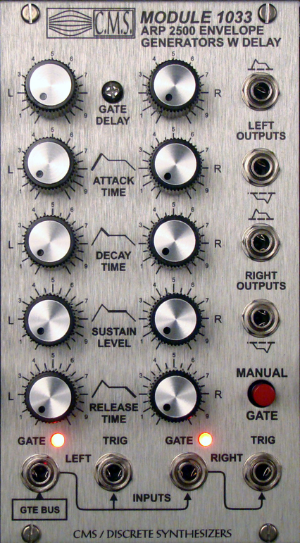
Sustain Level, and Final Decay Time. The panel graphics
emphasize the effects and use of each of these controls.
An envelope is initiated
when appropriate signals are applied to the Gate and
Trigger inputs. In the Module 1033 the control signal
which starts the envelope always passes through a delay
circuit which allows the user to postpone the beginning
of an attack from 3 milliseconds to 3 seconds by adjusting
the "Gate Delay" panel control.
When the Gate signal is
applied, the delay circuit is activated; after a time
period selected by the front panel "Delay Time"
control, the delay circuit produces a pulse which initiates
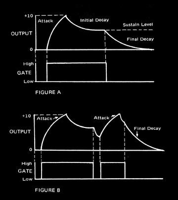
the attack. During the attack, the output of the envelope
generator rises exponentially to 10 volts at a rate
determined by the setting of the "Attack Time"
control. When the output of the envelope generator reaches
10 volts, the attack is ended and the output decays
exponentially to the "Sustain Level" at a
rate determined by the "initial Decay Time"
control. The sustain level is adjustable from 0 to 10
volts. The output remains at the sustain level until
the Gate is removed. When the Gate is removed, the output
immediately begins an exponential decay to 0 volts at
a rate determined by the "Final Decay Time"
control (Fig. A).
If the Gate voltage is
removed before the delay circuit has time to produce
a pulse, the delay circuit will be reset immediately
and will not produce a triggering pulse. Consequently,
no envelope will be produced.
If the Gate voltage is
removed during any part of the envelope cycle, the output
of the envelope generator will always return directly
to zero at the rate set by the "Final Decay Time"
control. Similarly, if the Gate voltage is reapplied
before the output returns to zero, a new attack will
begin after the time period specified by the "Trigger
Delay" control. The output need not return to zero
before the initiation of a new attack (Fig. B).

The gate
input is automatically patched to the trigger input
if there is no jack inserted into the trigger input.
This makes it possible to trigger an attack with only
a gate signal. To use a separate trigger, just simply
patch into the trigger input, otherwise it will use
the gate input as the source.
The presence of a Gate
signal or a Trigger pulse alone will not produce an
attack. A new attack is generated each time a Trigger
pulse is applied, and as long as a Gate signal is present.
It should be noted that the Trigger input is connected
to the input of the delay circuit which in turn triggers
the attack. Therefore an attack can be generated if
a Gate signal is present when the delay circuit produces
its pulse which may be some time later than the initial
trigger pulse.
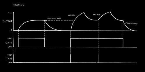
If the gate signal is applied
in the absence of a trigger, the output voltage will
rise to the sustain level at a rate determined by the
setting of the "Initial Decay Time" control.
The output voltage will remain at the sustain level
until the gate voltage is removed, at which time the
output voltage will return to zero at a rate determined
by the final decay control. (Fig. C).
 \ \
An inverted envelope with
output voltages from 0 to -10V is available for both
envelope generators.
The
ADSR circuits in this high quality module are exact
replicas of the ADSR circuits used in the ARP 2500 synthesizer.
The
C.M.S.1032 Dual Envelope Generator module features high
speed FET switching circuitry to produce extremely fast
response times. This is useful in generating high speed
percussive envelopes found in nature. Many synthesizer
designers have frankly underestimated the importance
that high speed envelopes have in defining the sound
of the instrument.
The
delay circuit is also useful in creating delayed or
slap back sequences similar to the sequence used on
Pete Townshends "Baba O'riley"
.
The high quality silver
anodized front panel facilitates easy comprehension
of the functions. The image is impregnated into the
surface of the metal. It will never wear off.
Sub-modular design for
easy service. High quality components assure decades
of reliable operation. |
